MENU
Speakers
Stepped Horn
Tapped Horn
Tuba36
Music
Bands
Software
Links
About Me
Tapped Horn Discussion
This is a speaker which I designed. It is based upon the 'tapped horn' principle (see Danley Labs 'tapped horn whitepaper'). First I will discuss a bit about my current thinking on 'tapped horns'. Some of this discussion assumes some knowledge of basic loudspeaker theory (in particular, for horn loudspeakers). It is recommended that you read Tom Danley's whitepaper, it is much better written, and gives a better overview of what this technology can achieve!
The inspiration was basically to have a go at designing my own loudspeaker for PA applications. I have always been a big fan of horn-loaded loudspeakers, the elegance of high efficiency and low distortion is very appealing. There is a rule of thumb as to what a loudspeaker can do, which more or less is 'low, loud, or small, choose two'. It is very difficult to get a very small, 'loud', loudspeaker which produces low frequencies very well. This is all subjective. However, for PA applications, I would classify 'small' as 2ft cubed, or thereabouts, 'low' as having decent low frequency reproductions below 50Hz, and loud, well, efficiency above 100dBSPL for 1W of input.
Horn loudspeakers tend to do the 'loud' part very well, but in order to produce low frequences have to be very large. The low frequency cutoff is considered to be a function of horn length and mouth area. The longer the horn, the lower the cutoff. The mouth area must be large enough to support this path length though, in order to get a proper flat response from the long path. Too small a mouth tends to produce dips in the response.
A tapped horn apparently can adequately produce LF with a smaller mouth area than a conventional front loaded horn. This has been discussed on the speakerplans.com forum, where a wealth of knowledge can be gleaned, as many people have discussed the principle.
Figure 1: Simplified diagram of horn loudspeakers with different mouth areas
It can be seen that for the same horn length, if a smaller mouth area is utilised, the volume of the whole system is much less. What does this mean? Smaller overall enclosure size for the speaker.
Designing a Tapped Horn
At the time of designing (around February 2007), not many DIYers had attempted to model tapped horns, or done much experimentation to my knowledge. There were the plans for the 'stepped horn' and also the work of William Cowan on tapped horns. Cowan had produced a few prototypes and discovered a way of predicting the response of the horn using HornResp.
Modelling the horn as a back-loaded conical horn at about a quarter wavelength of the desired low cutoff seemed to produce a good approximation as to what the response would be. A large dip would be pressent in the HornResp response, but this should be raised a bit by the 'tapping'. It was suggested that the two lowest peaks were made equal in amplitude.
The design constraints I placed on this speaker were as follows:
- Should use the Mivoc AWM104 loudspeaker since this was a cheap loudspeaker which i had another possible use for if it didn't work well in this project.
- Should be relatively small
- Should extend below 50Hz
In practise, the design I came up with could probably be bettered in terms of response and size. This didn't stop me ploughing full speed ahead with it, after all, this was an 'academic exercise' and if it didn't work, 'at least i'd learned something'.
The drivers used for the design cost me less than 50euros each, which is a big plus point for them, and i decided that due to their (low) lost, 2 of them could be implemented per cabinet. I think the price/performance of this design could be promising.
The Mivoc drivers I used are designed as 'car audio' drivers. They have a quoted Xmax of about 9mm, and sensitivity of 88dB. Some retrospective discussion on the speakerplans.com forum suggested that perhaps starting with a more efficient driver with less Xmax would be better, as overexcursion at LF is not such an issue with the tapped horn, by its very nature, it is good at controlling cone excursion. Anyway, at the time, I did not know this, (well, didn't think about it), and designed the system based on William Cowan's suggestions using HornResp. (In fact, thinking about it now, it's highly likely I did this incorrectly anyway!)
The design process went something like the following:
- Within HornResp, the radiation angle was set to half space. I think it is best to try and account for 'worst case scenario'.
- The horn was designed as a complete system. It was actually designed using 4 of the Mivoc drivers,wired parallel/series and allowing HornResp to calculate the equivalent single driver parameters. I am not sure how it does this, but I hope it is accurate and works in this situation.
- The horn parameters were played with until an acceptable predicted response was created. The total horn length was 2m, the throat 1600cm^2 and the mouth 4800cm^2. This gave a total system size of about 600l. It was decided to achieve these volumes across 2 seperate cabinets, for ease of transportation/use. Each would have 2 of the drivers, wired in seried.
Playing around with throat/mouth sizes, number of drivers etc I achieved a response I hoped would yield adequate results. The predicted response was as follows:
Figure 2: Hornresp predicted response for my tapped horn
Hopefully the dip would reduce, and good response in the 45Hz-120Hz range could be achieved.
The HornResp input screen was as follows:
Figure 3: Hornresp input parameters
The speakers were designed to be used in a system of at least 2 boxes, each roughly 60cmx60cmx110cm.
A sketch of the system was made in Google Sketchup. All the parts are 60cm wide.
Figure 4: Google Sketchup model of the internals of the tapped horn (click)
The sketch is not 100% accurate but I had a mental image of what went where, so was adequate for me.
The Build Process
Some photos from the build process can be found on the speakerplans.com forum here.
What does it sound like?
At the time of writing, only one of these tapped horns had been produced. It was designed to be used in pairs. Subjective listening results are poor. Listened to alongside a single Tuba36 folded horn (also designed to be used in multiples), the Tuba sounded much fuller, and louder. Curious as to whether building the other half of the pair will improve performance, I have started building another, but as yet havn't had time to complete it. Modelling the equivalent 'half horn' with 'half driver' parameters, gives similar results to those of the full system, so I am doubtful as to whether it is an 'insufficient mouth area' issue, as I first suspected upon hearing the horn.
What happened?
I suspect that I did not model the horn correctly as per William Cowans Model. Cowan has since written about a new, more reliable method for modelling tapped horns, (actually credited to David McBean), using AkAbak. Attempting to use this method (using the composite driver parameters produced by HornResp), the following response curve was produced:
Figure 5: AkAbak predicted response for tapped horn (click)
This looks a lot more like what I was hearing. A 10dB dip at 60Hz is a huge ammount. It seems my version of the tapped horn did not remove the dip! It may be possible to correct this using EQ, but even so, it is not what one would hope for! At least the HornResp model predicted cutoffs the same at the AkAbak one! The script which produced the above plot is here.
It should be noted that the above simulation the voltage is 0.707v. With 1W input, (2V, 4ohm load), the dip is about 97dBSPL, which might still be acceptable efficiency. I am unsure what the effect of EQ on this would be.
What is noticeabley different with my tapped horn compared to Walt and William's, is the direction of the speakers. If you look at the others', the speakers fire directly out of the mouth of the horn, whereas mine are rotated 90degrees to this. I can't think of a reason as to why this would be significant to the output though.
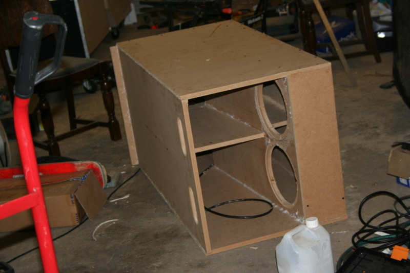
Figure 6: Finished tapped horn before drivers are loaded (Click)
Also, the throat on mine is much larger than the other designs I've seen. Reducing this in AkAbak significantly raises the dip, although the LF cutoff is raised too. The design also extends higher. It seems that a very good 'kick bass' horn might be possible yet, going with similar.
More Tapped Horn Modelling

Figure 7: Google sketchup model of tapped horn with 4m path (4 of these are required) (click)
I did some more modelling in AkAbak, and managed to produce a model which should theoretically give a 97dBSPL sensitivity across the range roughly 30Hz to 80Hz. The -3dB point is 27Hz. Although not hugely efficient, they are the same theoretical size as the original tapped horn design. Again, the boxes are designed to be used in pairs, each with dual 10" drivers. The path length is about twice as long as the original design, with a much smaller start and end cross sectional area. The script used to produce the followinf response in AkAbak can be found here.
Figure 8: AkAbak predicted response for 4m tapped horn (click)
Compare this to another sub with a similar LF response, the X1. The X1 has about 5dB more sensitivity, which means it will take a lot less than half the power to reach the same SPL level. It also plays up to about 119Hz, (although I think the advice is to cross over lower than this). To be honest, the performance is far below that of the X1 (or similar, well designed subwoofers). The only reason to build this one, over the X1 would be for cost of drivers (about £120) wheras the
P-Audio SD18 (recommended X1 driver) costs around about £220. An X1 occupies about 370l, and a pair of these tapped horns occupy about 530l. I suppose building 4 of the double driver boxes would give very good bass in the 27-80Hz range, and if i get time I may try this new design with extra folds.